Properly and strategically placed satellite receiver bays extend the useful range of walkies and insure perfect reception. Repeater transmitters can be placed at locations where they have the best range and penetration into buildings.
Voting systems can be integrated with repeaters, or they can be integrated with stand-alone transmitters.
Voting Receivers
Voting systems utilize special receivers, called Satellite receivers; and Voting Comparators. Satellite receivers are connected back to a comparator at a central point by way of microwave links, phone lines, or voice circuits on T-1's.
Voting systems can cover a large geographical area (county or area-wide), or they can be concentrated to provide absolutely solid portable communications in a small area (city-wide).
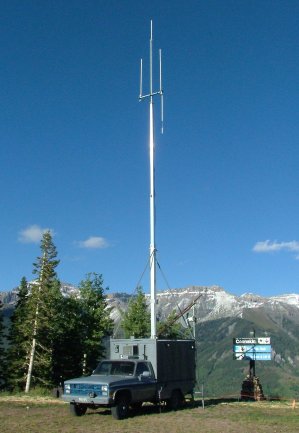
Transmitter truck at 10,500 ft.
Each channel in a system which is to be voted has receivers at several locations in the
coverage area of the repeater transmitter. If there are 6 channels to be voted, each
channel has a receiver in each location.
Each satellite receiver places a signal on the audio circuit which indicates that it is idle (no signal). The comparator senses that signal and is idle also. When a user transmits, he will hit several receivers at once on that channel. One of those receivers will have the best signal. The comparator chooses or "votes for" the receiver with the best signal quality and routes the audio to the transmitter.
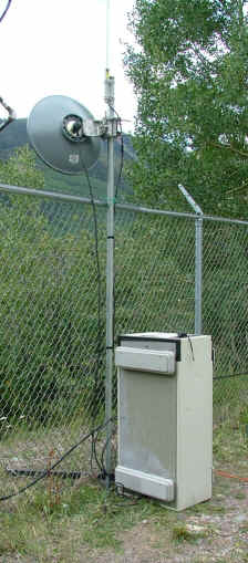
Temporary Receiver Bank Emplacement
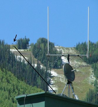
Roof Of Dispatch location.
The left path (black line) goes to the truck (above left) and the right path goes to a remote receiver location (above right)
The comparator looks at the audio from all the receivers and "votes" for the one with the best signal-to-noise ratio. The comparator sends a signal to the transmitter causing it to key up and then routes the receiver audio to the transmitter. The comparator continues to examine the signals from all the receivers during the transmission. If a different receiver begins to hear the user better than the original voted receiver, the comparator will switch to that receiver without interrupting the transmission. This switching between receivers may occur several times in a few seconds. When the system is properly set up, the switching is inaudible and transparent.
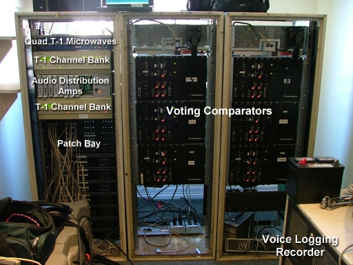
Motorola Digitac Digital Voting Comparators
Comparators are connected to dispatch consoles